Lithium-ion batteries (LIB) are used over a wide range of applications, from small mobile communication devices, to power tools, home battery storage for photovoltaic energy up to electric cars and trucks. Every li-ion battery consists of multiple cells which are connected in series and parallel, according to the requirement of the application. A battery management system (BMS) is used to observe the battery and operate it in safe environment. The BMS often measures the cell voltages, temperature and the pack current. Different algorithm on the BMS calculate then the state of charge (SoC) state of health (SoH) and state of function (SoF). Those algorithm uses different cell parameters which are nowadays determined in the laboratory. Especially if the SoC and SoH algorithm must cover calendar life time and cycle life time, then the cells often are tested over a long time (+2 years) under constant environment conditions. This parameter identification for one cell type is an expensive and time-consuming work. It could be minimized if the battery model can be adjusted automatically from time to time over the air.
The internet of things (IoT) allows us to collect and store the ubiquitous data coming from pervasive batteries and their BMS. With traditional algorithm and machine learning it is possible to extract the battery parameters with respect to the different purposes. The parameters can then be transmitted back to the battery to calculate a more accurate and satisfactorily estimation of SoC and SoH.
With gained experience from older batteries, we can develop more robust and accurate battery model in shorter time.
In this project an IoT application is created to demonstrate the combination of a battery management system (BMS) with IoT. The sensor node communicates over LoRa with the LoRaWAN gateway which is connected to The Things Network (TTN). On TTN the messages are decoded and published over the machine to machine protocol MQTT. Two MQTT subscribers are implemented, one is hosted on Amazon Web Services (AWS) and the other is implemented on a Linux machine with Node.js.
Both applications must fulfill the following requirements:
- store measured data in a database
- process data with Python in Jupyter Notebook to extract the battery parameters
- show information on a simple dashboard
The communication for sending the cell / battery parameters back to the BMS is not implemented.
IoT Applications – Recurring Patterns of IoT
To figure out the benefits of an IoT-Battery we must find the general patterns of IoT. We find them also in products and services of major innovative companies.
- Remote expertise and control
- Operational analysis and alarming
- Sharing / mobility
- Supervision for guarantee
- … as a service (pay as you use)
A successful IoT project gives the customer added value in the following aspects:
New Functions
- The measurement data from thousands of cells / batteries can be used for cell parameter estimation. Machine learning and predictive modelling can be used due to the large dataset. The data is also available for traditional electrochemical cell modeling.
- The cell parameters can be used for further developments of cells, cell chemistry and packaging.
- The battery management system (BMS) can be updated over the air with the new cell parameters.
- The battery manufacturer can see when the battery has been used outside the given specifications. He can therefore reject any warranty claims.
Higher Efficiency
- There is no need for time-consuming testing on expensive laboratory equipment to determine the parameters of the cells.
- Detection of aged batteries and automatic offering a new one. Since the data of the application are available, we might be able to propose a better one.
- Preventive maintenance due to anomalies in the measured data, no unforeseen downtimes of the application.
New Business Models
- Renting batteries instead of selling them. Settlement according to consumption and usage:
- Charged/discharged energy/capacity
- Deep of discharge (DoD)
- Shallow cycles
- High current peaks
- High/low temperature
- In logistics centers, routes of industrial trucks can be optimized in order to distribute the deep of discharge (DoD) equally. This guarantees a longer battery life and minimizes maintenance costs.
- Lease back of second live batteries.
- Consulting and recommendation of operational improvements.
Implementation
Network
As network The Things Network (TTN) is used due to the good documentation and the supportive community.
Gateway
As LoRaWAN gateway I use the RAK831 which can be found on Aliexpress. The RAK831 LoRaWAN gateway can be mounted on a Raspberry Pi.
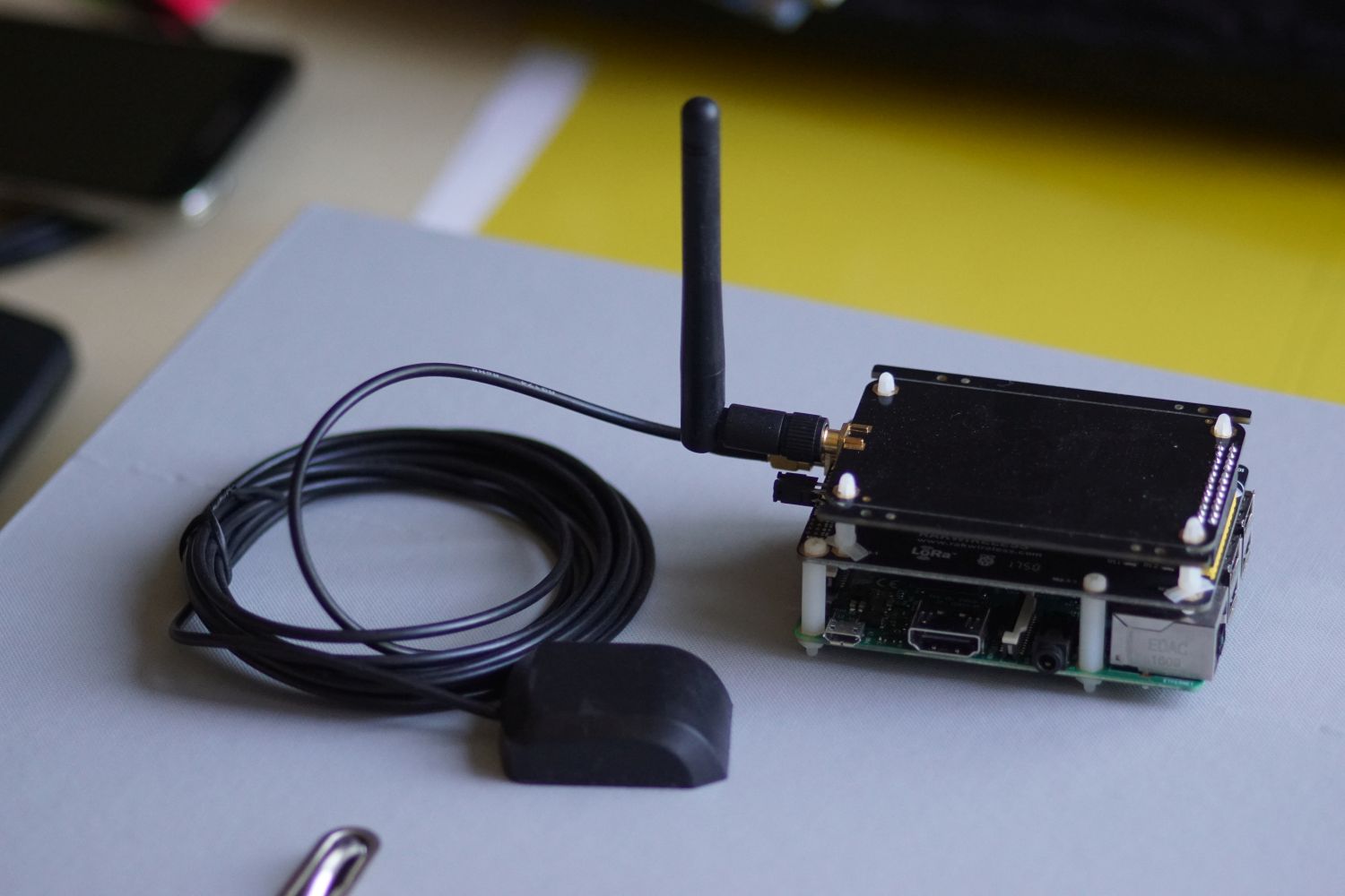
In Europe the SRD-band 863-870MHz (868MHz) is used for LoRA. This device can be used as a gateway for The Things Network. The ttn-zh group provides on their GitHub page the necessary source code based on the iC880a gateway. I followed this tutorial , where a step by step instruction guideline can be found, how to set up the RAK831 for TTN. I had troubles to compile the C-code for resetting the gateway. With the following code it should work:
#include <wiringPi.h>
#include <unistd.h>
#define GPIO_RESET_PIN 0 // see wiringPi mapping!
int main() {
    wiringPiSetup();
    pinMode(GPIO_RESET_PIN, OUTPUT);
    digitalWrite(GPIO_RESET_PIN, HIGH);
    sleep(5);
    digitalWrite(GPIO_RESET_PIN, LOW);
    return 0;
}
I added the following line to /etc/rc.local this will reset the RAK831 after a bootup of the Raspberry Pi.
# Reset RAK831 Gateway at bootup
/home/pi/RAK831_reset
The Raspberry Pi can be connected with a network cable to the router at home.
Sensor Node
Because I currently have no BMS available I use an Arduino, as mockup, on which I generate the battery management system (BMS) relevant information myself. The State of Charge (SoC) for example can be emulated with a potentiometer. The other values are either constant or uniform random variables.
To connect the Arduino with the LoRaWAN gateway I use the LoRa shield from Dragino which can be mounted on top of the Arduino. The LoRa shield uses the RFM95W transceiver module from HopeRF. It costs on Digikey1 is below 14CHF for one piece.
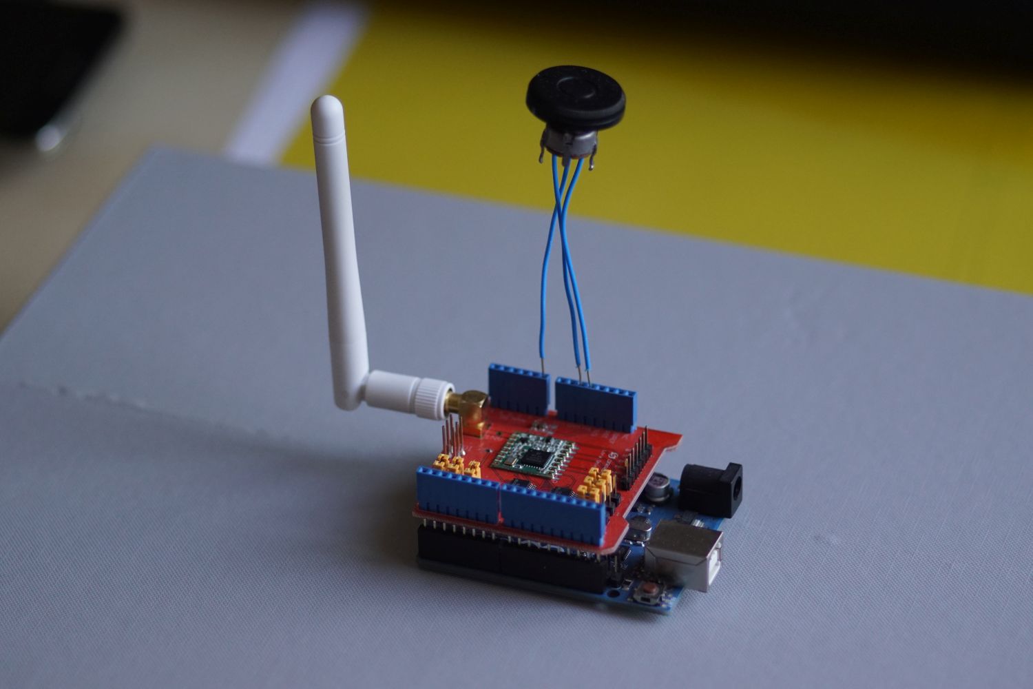
On the Arduino I use the arduino-lmic library2. It is the adapted IBM LMIC library3 for Arduino. The data packet is sent every minute.
For the final product, the transceiver can be soldered directly to the BMS. Then the BMS can communicate over SPI with the transceiver.
To connect the sensor node to TTN we must create an application in the TTN console. Under devices we can add a new device. We then get the Device EUI the Network Session Key and the App Session Key. All three information are used for the LMIC library.
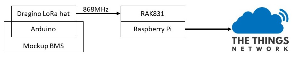
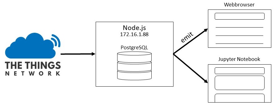
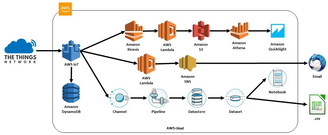
After those steps we have a setup as shown in the picture below. Data from the mockup BMS will be sent by the Arduino over LoRA to the LoRaWAN gateway. The Gateway then pushes the messages to The Things Network (TTN) from where it can be accessed over MQTT.
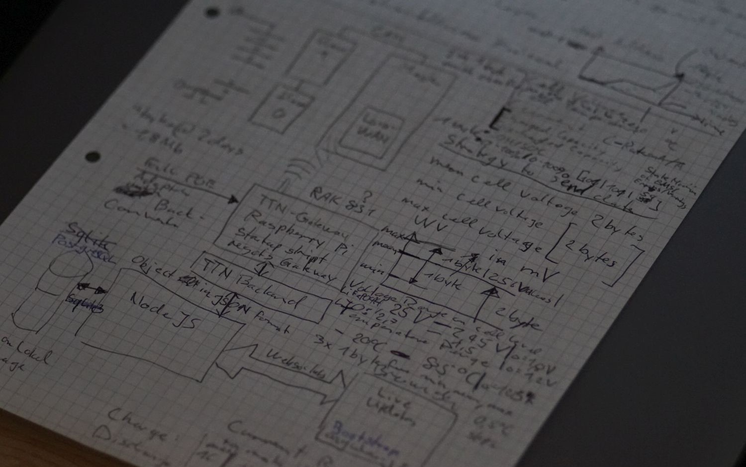
Data design
The following values should be transferable from the sensor node to the backend:
- Mean cell voltage, maximum voltage, minimum voltage
- Mean cell temperature, maximum temperature, minimum temperature
- State of Charge (SoC), State of Health (SoH)
- Charged capacity, discharged capacity
To increase the entropy of the transmitted data, the following encoding will be applied. For the mean cell voltage, we have a high resolution of 16 bits. Such a high resolution is chosen because the pack voltage can also be calculated from this data. If a pack consists out of 100 cells in series we will lose the resolution of the factor 100. The min and max cell voltage are in respect to the mean cell voltage. The maximal deviation in both directions is 250mV. With this trick we don’t spend the same numbers of bits like for the mean value.
For the temperature the same idea is used. Here we do not need such a high accuracy as with the voltage, since the temperature measurement is not as accurate.
The SoC and SoH normally are given in 1% steps so we need 7 bits each. The last bit of the byte could be used for indicating a state of the BMS.
The charged and discharged capacity is given with the unit Ampere-seconds (actual current divided by nominal current at 1C multiplied with the time in seconds, see equation: $\ref{ref:cs}$). For general use we can normalize the capacity of the battery to 1Ah then we can use the same coding for different sized batteries. If we want a minimal resolution of 1As/bit we can go with 8 bytes up to a little bit more than 4C. Li-ion battery normally are not charged with a higher C-rate than 1. Therefore, we can limit the number of bits for charged capacity to 6. The remaining 2 bits can be used for example to send information about the state machine on the BMS.
If the charge or discharge current go beyond 1C respective 4C we will have an overflow on those variables. We can detect such an overflow with a faster changing SoC and a higher voltage drop. This must be implemented on the application side.
| Variable | min value | max value | delta | # bits | resolution |
|---|---|---|---|---|---|
| voltage_mean | 2.45V | 4.25V | 1.8V | 16 | 0.027mV/bit |
| voltage_min (difference to mean) | -0.25V | 0V | 0.25V | 8 | 0.977mV/bit |
| voltage_max (difference to mean) | 0V | 0.25V | 0.25V | 8 | 0.977mV/bit |
| temperature_mean | -20°C | 80°C | 100K | 10 | 0.097656K/bit |
| temperature_min (difference to mean) | -20°C | 0°C | 20K | 7 | 0.156250K/bit |
| temperature_max (difference to mean) | 0°C | 20°C | 20K | 7 | 0.156250K/bit |
| SOH | 0% | 100% | 100% | 7 | 1%/bit |
| SOC | 0% | 100% | 100% | 7 | 1%/bit |
| capacity_chg | 0As | 64As | 64As | 6 | 1As/bit |
| capacity_dsg | 0As | 256As | 256As | 8 | 1As/bit |
With this design we send 11 bytes from the sensor node to the Gateway. The decoding function on TTN looks like the code snippet below. The encoding of the most significant bit (MSB) of SoC and SoC for the state indication has not been implemented yet.
The min and max correction according to the mean value for voltage and temperature is already implemented in this function.
function Decoder(bytes, port) {
    var temperature_mean = -20 + ((bytes[0] << 2) + ((bytes[1] & 0xC0) >> 6)) * 100 / 1024;
    var temperature_min = temperature_mean - (((bytes[1] & 0x3F) << 1) + (bytes[2] & 0x01)) * 20 / 128;
    var temperature_max = temperature_mean + (bytes[2] & 0x7F) * 20 / 128;
    var cell_voltage_mean = 2.45 + ((bytes[3] << 8) + bytes[4]) * 1.8 / 65536;
    var cell_voltage_min = cell_voltage_mean - bytes[5] * 0.25 / 256;
    var cell_voltage_max = cell_voltage_mean + bytes[6] * 0.25 / 256;
    var soc = bytes[7];
    var soh = bytes[8];
    var charged_capacity_1cs = (bytes[9] & 0x7F);
    var discharged_capacity_1cs  = bytes[10];
    return {
        measurement: {
            temperature_mean: Math.round(temperature_mean * 100) / 100,
            temperature_min: Math.round(temperature_min * 100) / 100,
            temperature_max: Math.round(temperature_max * 100) / 100,
            cell_voltage_mean: Math.round(cell_voltage_mean * 1000) / 1000,
            cell_voltage_min: Math.round(cell_voltage_min * 1000) / 1000,
            cell_voltage_max: Math.round(cell_voltage_max * 1000) / 1000,
            soc: soc,
            soh: soh,
            charged_capacity_1cs: charged_capacity_1cs,
            discharged_capacity_1cs: discharged_capacity_1cs,
        },
    };
}
In the TTN console we can now see the JSON formatted incoming data. On the right side we can also see the Metadata from the Gateway where the time is given.
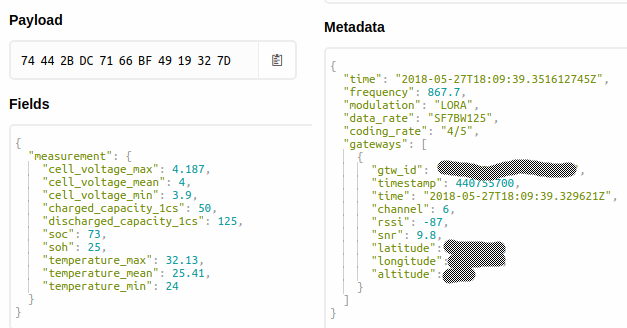
With this configuration the manufacturer of the battery must note down the setup of the cells (parallel and serial connections) and the nominal capacity. With this information we can later calculate the pack voltage and the current of the battery.
Backend
Own implementation
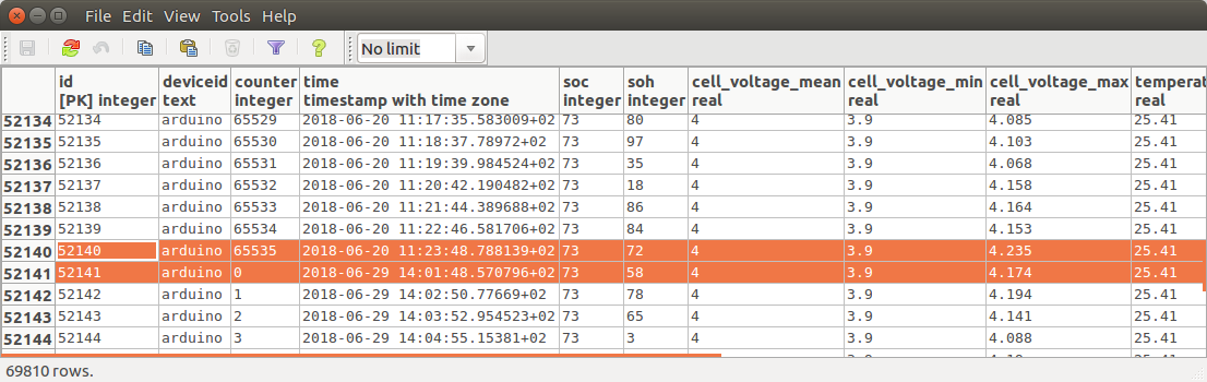
TTN provides various APIs like Go, Java, Node-Red and Node.js. Because most examples on the internet are implemented with Node.js I will use this API. As backend a virtualized Ubuntu server is used. For storing the received values, a PostgreSQL server is installed on the same machine.
Website
The data is made available to the user on a website. The communication between the server and the website is realized with web sockets. The website uses AngularJS for the dynamic table and bootstrap is used for a nice and modern look.
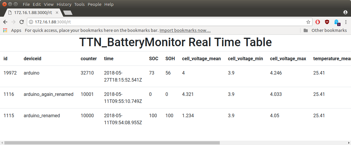
If a new message arrives over MQTT it will be stored in a SQL table and then emitted to the connected browsers. The query for the latest information from each node ordered by the device name looks like the code snippet below. This query is executed whenever a new message over MQTT arrives or a new browser connects to the webpage. For larger systems, with more sensor nodes, a better strategy must be developed.
SELECT DISTINCT ON (deviceid) *
    FROM measurements
    ORDER BY deviceid, "time" DESC;
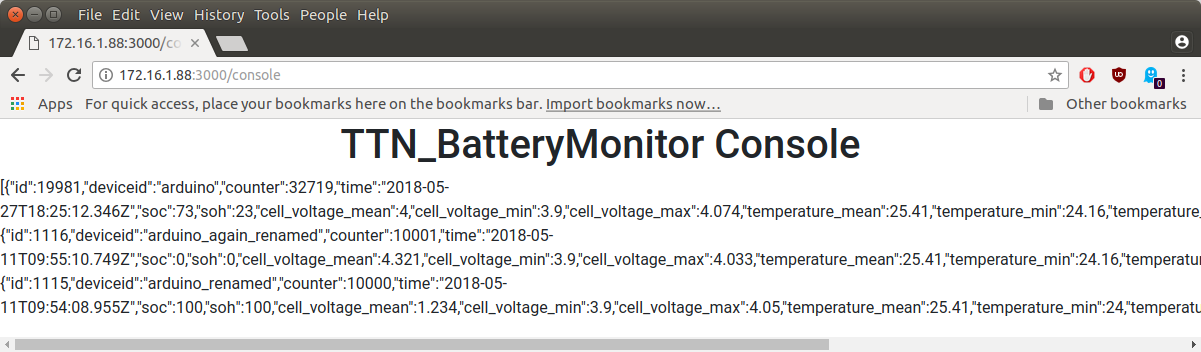
On the website there is also a console like in TTN, where the entire JSON string is published. This can be useful for debugging and finding errors. The JSON strings are stored in a different SQL table. We may later be able to use the position of the gateway that received the node message.
Jupyter Notebook
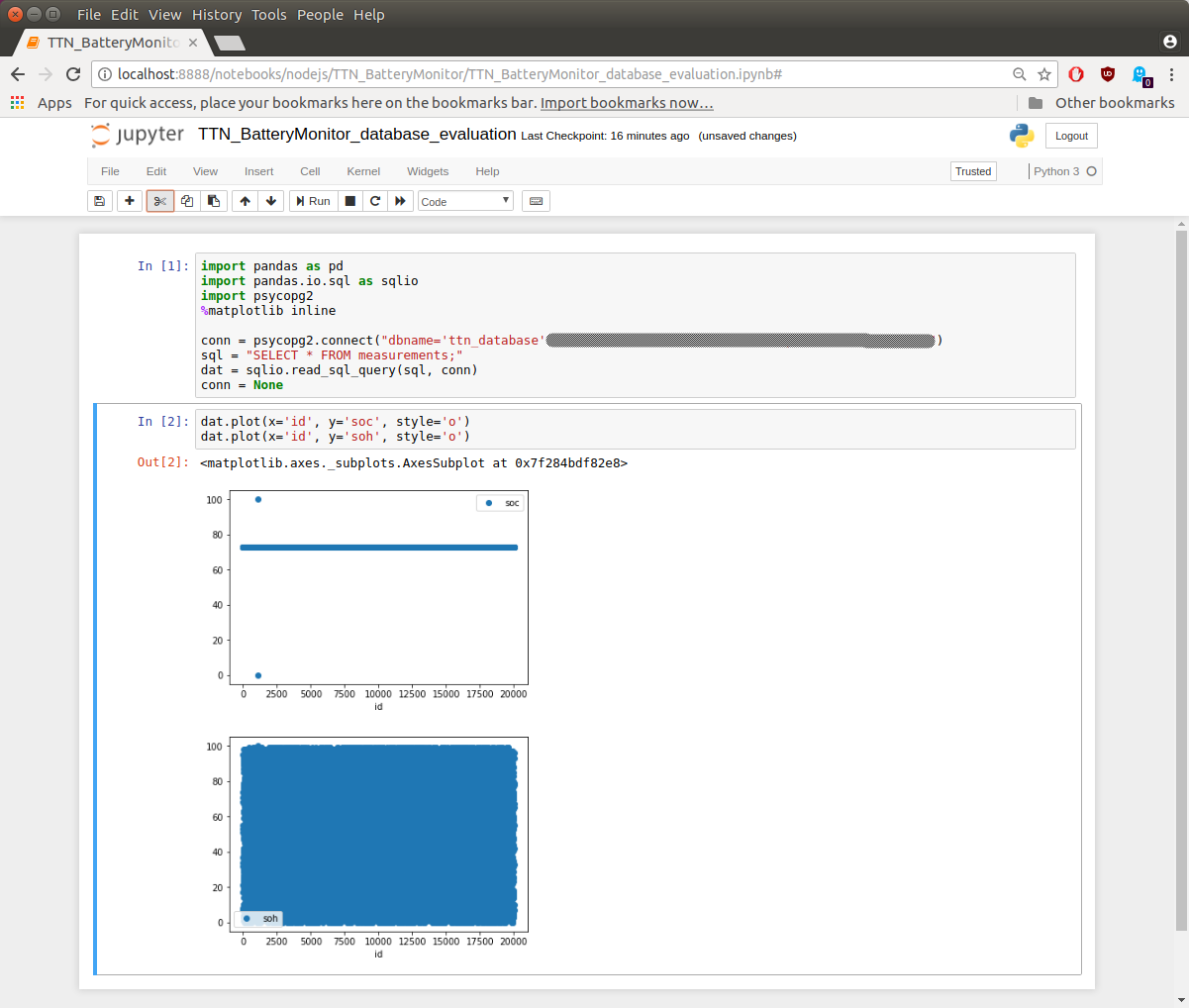
The data on the SQL server is also available for other applications. With Jupyter Notebook and the psycopg2 library we can access them and use it for example with TensorFlow or SciKit Learn to model the battery parameters. In the picture below the SoC and SoH are plotted to test if the values are extracted correct.
Install backend
The own implementation is available on GitHub:
https://github.com/danislab/TTN_BatteryMonitor
To install the software you need Node.js and PostgreSQL running on your server.
Choose your desired location and enter npm install to install the necessary packages.
In the file db/index.js you can adapt the settings for you SQL server.
To start the backend simply run node .
Amazon Web Services (AWS)
I also tested the AWS IoT platform. The integration of TTN can be done according to this instructions . After adding the device, we can add different rules how the MQTT messages should be handled.
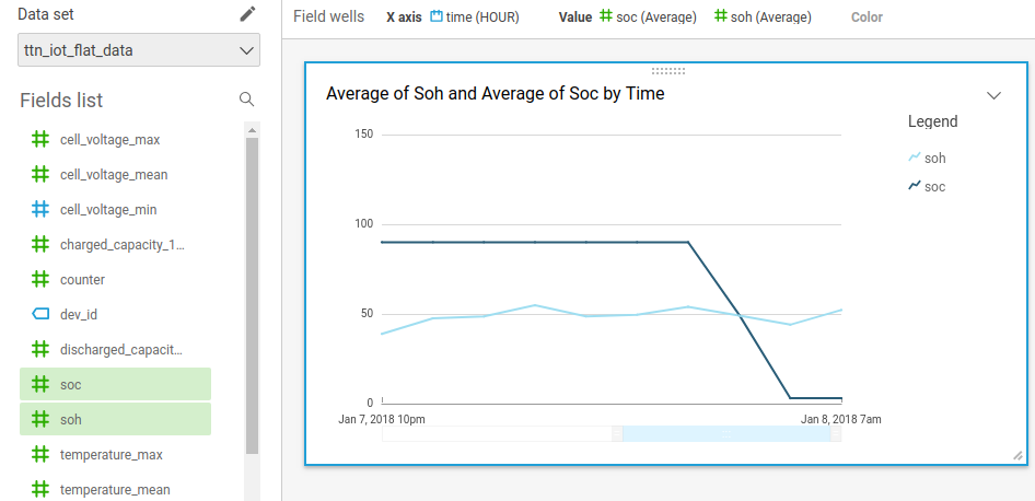
In the picture below, we can see that the messages are stored in a DynamoDBv2 like the PostgreSQL in the own implementation. Further we can publish the messages with QuickSight in a nice time dependent plot, send a notification or prepare the data to be processed in a Jupyter Notebook running on Amazon SageMaker.
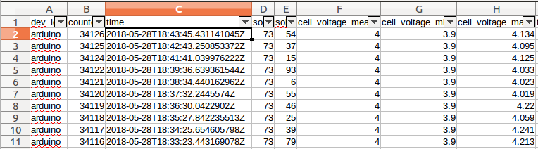
Store data in a SQL database
The goal is also here to store the incoming data into a database. First, we must extract the important information from the incoming JSON string. We can use the following command to retrieve the necessary information.
SELECT
    dev_id,
    metadata.time,
    payload_fields.measurement.soc,
    payload_fields.measurement.soh,
    payload_fields.measurement.cell_voltage_mean,
    payload_fields.measurement.cell_voltage_min,
    payload_fields.measurement.cell_voltage_max,
    payload_fields.measurement.temperature_mean,
    payload_fields.measurement.temperature_min,
    payload_fields.measurement.temperature_max,
    payload_fields.measurement.charged_capacity_1cs,
    payload_fields.measurement.discharged_capacity_1cs
FROM 'danislab_test_application/devices/+/up'
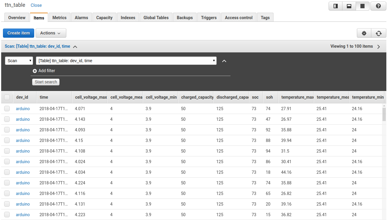
The action “Split message into multiple columns of a database table (DynamoDBv2)” is used. Thus, the received data is saved directly in a previously created DynamoDB table. The table with the entries are shown in the picture below.
IoT Analytics
In the end of April 2018 Amazon made the ASW IoT Analytics generally available4. I found the following picture on the start page of AWS IoT Analytics5, it describes exactly what I want to achieve to extract the battery parameters.
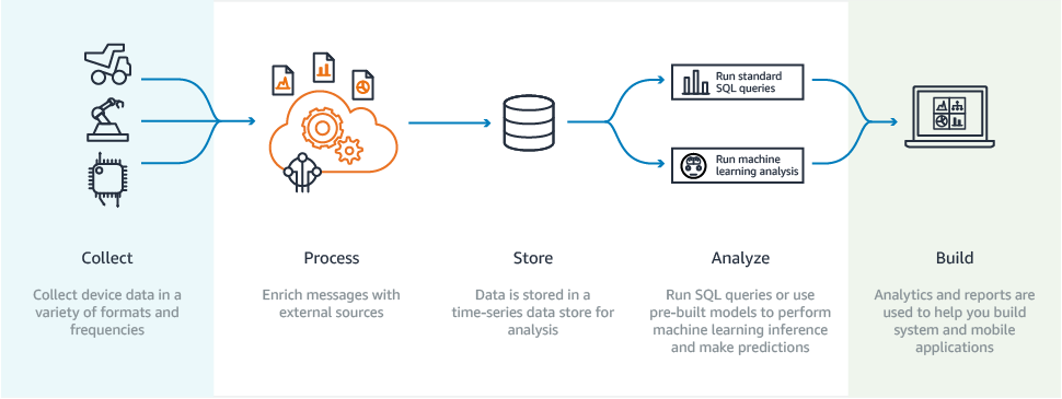
- Collect: Collect the data from different batteries and the assembly information
- Process: Calculate the current with charged / discharged capacity, calculate the pack voltage
- Store: Store all values in a defined format (relation to physics)
- Analyze: Determine the battery parameters with machine learning
- Build: Create and dashboard or app where all important information is listed live. If a threshold is reached an alarm can be triggered.
So, I started to integrate my IoT Core to Analytics with the help of this Workshop6. First, I created a channel, a pipeline and a datastore to store all necessary values in a dataset. The dataset can be processed in a Jupiter Notebook instance or exported as .csv file.
QuickSight
To make the data visible on a dashboard I use a AWS Kinesis Firehose Delivery Stream where I adjust the streamed data with the following Lambda function.
'use strict';
console.log('Loading function');

exports.handler = (event, context, callback) => {
    /* Process the list of records and transform them */
    const output = event.records.map((record) => {
        const entry = (new Buffer(record.data, 'base64')).toString('utf8');
        let ttn_json = JSON.parse(entry);
        let ttnDeviceTime = ttn_json.metadata.time
        let year = new Date(ttnDeviceTime).getUTCFullYear();
        let month = new Date(ttnDeviceTime).getUTCMonth()+1;
        let day = new Date(ttnDeviceTime).getUTCDate();
        let hours = new Date(ttnDeviceTime).getUTCHours();
        let minutes = new Date(ttnDeviceTime).getUTCMinutes();
        let seconds = new Date(ttnDeviceTime).getUTCSeconds();
        let date = year + "-" + month + "-" + day + " " + hours + ":" + minutes +":" + seconds

        let flat_json = {
            time: date,
            time_orig: ttn_json.metadata.time,
            dev_id: ttn_json.dev_id,
            counter: ttn_json.counter,
            soc: ttn_json.payload_fields.measurement.soc,
            soh: ttn_json.payload_fields.measurement.soh,
            cell_voltage_mean: ttn_json.payload_fields.measurement.cell_voltage_mean,
            cell_voltage_min: ttn_json.payload_fields.measurement.cell_voltage_min,
            cell_voltage_max: ttn_json.payload_fields.measurement.cell_voltage_max,
            temperature_mean: ttn_json.payload_fields.measurement.temperature_mean,
            temperature_min: ttn_json.payload_fields.measurement.temperature_min,
            temperature_max: ttn_json.payload_fields.measurement.temperature_max,
            charged_capacity_1cs: ttn_json.payload_fields.measurement.charged_capacity_1cs,
            discharged_capacity_1cs: ttn_json.payload_fields.measurement.discharged_capacity_1cs,
        }

        const payload = (new Buffer(JSON.stringify(flat_json), 'utf8')).toString('base64');
        return {
            recordId: record.recordId,
            result: 'Ok',
            data: payload,
        };

    });
    console.log(`Processing completed.  Successful records ${output.length}.`);
    callback(null, { records: output });
};
The adjusted JSON string is then stored in an S3 bucket. Athena is used to query data from S3 to present it on QuickSight. Unfortunately it seems like the minimal time resolution is hourly.
E-mail notification
With the following Lambda function and the Amazon Simple Notification Service (SNS) it is possible to send an E-mail if a value is below a defined threshold. in the example below an E-mail is sent if the SoC is below 3%. This can be helpful to avoid deep discharges of batteries in the field. In my example an E-mail is sent if the State of Charge (SoC) is less than 3%. I can emulate and test this by turning the potentiometer to the minimum.
console.log('Loading function');

var topicArn = 'arn:aws:sns:eu-west-1:318624989995:ttn_alarm_battery';
var AWS = require('aws-sdk');
AWS.config.region = 'eu-west-1';

exports.handler = function(event, context) {
    var sns = new AWS.SNS();

    let ttnMessage = event;
    let soc = ttnMessage.payload_fields.measurement.soc;
    let device = ttnMessage.dev_id

    console.log('The SoH for ' + device + ' is ' + soc + '%');
    if(soc < 3) {
        sns.publish({
            Message: 'The SoH for ' + device + ' is ' + soc + '%',
            TopicArn: topicArn
        }, function(err, data) {
            if (err) {
                console.log('Error while sending alarm');
                console.log(err.stack);
                return;
            }
            console.log('alarm sent successfully');
            console.log(data);
            context.done(null, 'Function Finished!');
        });
    }
};
Comparison
It is time consuming to design your own application. The advantage is that you can build it in that way you want. The disadvantage is that you must know everything from MQTT, Node.js, SQL, infrastructure to web-design.
If you use a platform like AWS, Azure or IBM Bluemix you must know that you are always addicted to them. There exists a so-called lock-in effect. The advantage is that their service is scalable and for small systems relative cheap.
For me it is the first time that I use AWS. In the beginning AWS seemed very complex but with the time I became more familiar with the AWS ecosystem. I think a person who works daily with AWS could build a fully automatic and scalable IoT Battery platform.
Costs
The total costs of this project are 244 CHF. The most expensive part is the Gateway. In this project I had only one sensor node, therefore the cost of 24.25 CHF for AWS seems quite high.
| Position | Price |
|---|---|
| Raspberry Pi 3 | 29.00 CHF |
| SD Card | 15.40 CHF |
| RAK831 | 144.05 CHF |
| Arduino Uno | 14.95 CHF |
| Dragino LoRa Hat | 16.50 CHF |
| AWS | 24.25 CHF |
| Total | 244.15 CHF |
Mistakes
The counter for messages on the Arduino has 16 bytes. When the overflow happened, the entire software crashed. In a real-life application this would be the worst case because the batteries would be distributed around the world and it would not be easy to update the software or reset the node. You can also see that it took more than nine days until I discovered this malfunction. A watchdog should be implemented to detect such events.
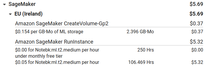
When I was playing around with Jupyter Notebook in SageMaker I never stopped the instance. After reaching the free tier limit, Amazon charged me with $0.05/h although nothing was running.
Conclusions
We have seen that today it is very easy do implement an IoT battery application for demonstration. A lot of services are available from open-source project to products from global player companies.
IoT can be easily adapted to batteries because the energy source is always available and the energy consumption for the IoT part is only a fraction of the whole consumption of the application. For stationary battery the connection to the backend can also be realized with a traditional internet connection. For mobile applications a wireless solution is needed. In our example we used LoRaWAN with the frequency range of 863 - 870MHz. In other countries different frequency bands are allowed. This makes it not easy for a manufacturer who ships the product internationally. Only the 2.4GHz band is allowed worldwide.
This is just a demonstration project, for large systems we must consider also other topics and challenges:
- How can I guarantee that the communication channel is always available? What happens if the communication cannot be established? Should I store the data on the device which could not be sent to the backend? How can I transfer that information if I use a low bandwidth channel for instance LoRaWAN?
- In this application I used the timestamp from the gateway because I have no clock on my battery. If I store the values on my battery I need a time. From where does this clock signal come? When I use a real-time clock (RTC) IC I must synchronize it somehow due to the drift of the RTC.
- What happens in the application if some data is missed? Do I just skip this part or can I interpolate the missing values? What if the data arrive after an interpolation?
- How is the process if a battery is replaced? The battery producer is interested in the data regarding this particularly battery. The user however is interested in the data of the application. What if the battery is replaced by one with a higher capacity, how does the backend will be informed about the changing capacity? The change of the capacity must be registered when the change happened and not when the service technician makes the change in the evening after work.
- Security: what happens if someone steals my keys which are on the sensor node? He can now also push messages to the backend. How are the data on the backend secured? The service technician should have access to all his installed batteries, the user in contrast should only have access to his purchased batteries.
- Is it necessary to send data every minute? If for example the battery is idle over night or in a warehouse then it isn’t important to send data with this interval. Therefore, a dynamic model like a discrete event system according to Dijkstra would be appropriate. The data transfer can be described like a communicating sequential processes (CSP) according to Charles Antony Richard Hoare7.
- Supposed I sell the batteries labeled with predictive maintenance and the correct estimation of failing batteries is 99%. If I sell 100'000 batteries then 1'000 will not detect the failure. The customers of the 1'000 batteries will not be happy about this and the other 99% will not notice that the estimation was correct. Maybe a label like smart monitoring would be better.
In this project, only the path from device to backend has been realized. The path back for sending the battery parameters must be implemented.
We can see that IoT is not just to push some data to the cloud and plot the values. Many clarifications and developments are still necessary for a real product with added value. I propose the following strategy for future development of BMSs with IoT functionalities:
- Use the standard patterns for safety functions like over- / under voltage protection on cell / pack level, over- / under temperature protection, overcurrent protection.
- Use model parameters calculated from 100, 1'000, … , 100'000 batteries operated at different conditions to calculate SoC and SoH.