Today I would like to share my experience of initializing a bus signal in Simulink based on a struct from the Matlab workspace. For me, the instructions in the documentation and on the internet were not so clear. I will therefore show an example of how this can be implemented. I use this appraoch for an extended Kalman filter (EKF) and unscented Kalman filter (UKF), where I need to initialize the initial states of the estimation algorithm.
Create Model and Estimation Data Struct in Matlab
First we will create two structures, the first to describe the model and the second to combine all important data for the estimation algorithm.
Thereby the model struct is nested in the estimation struct.
The function Simulink.Bus.createObject() creates a Simulink bus object based on a Matlab structure.
According to my findings the created bus is always named slBus1 and stored in the base workspace.
This leads to problems, especially when creating a bus within a function.
For this purpose the created bus with the name slBus1 is copied into a new variable with the unique named estData_bus.
Then the bus slBus1 is deleted from the base workspace to achieve a clear order.
The example shown here can therefore also be called within a function.
% Create Model Struct
model_struct.mod_var1 = 2;
model_struct.mod_vec1 = [1, 2, 3];
model_struct.mod_array1 = eye(3,3);

% Create Estimation Data Struct
estData_struct.est_var1 = 5;
estData_struct.est_vec1 = 5 * [1, 2, 3];
estData_struct.est_array1 = 5 * eye(3,3);
estData_struct.model = model_struct;

% Create Estimation Data Bus for Simulink Model
estBusInfo = Simulink.Bus.createObject(estData_struct);
estData_bus = evalin('base', estBusInfo.busName);

% Delet created Bus from base workspace
evalin('base', 'clear slBus1' );
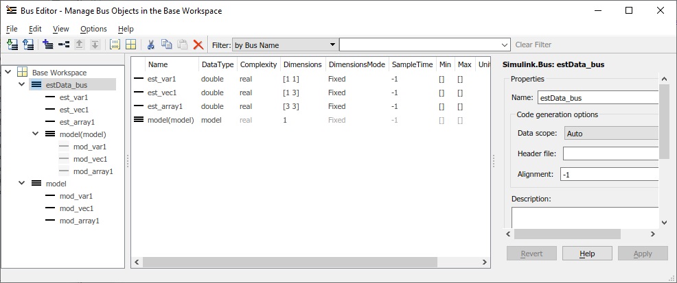
From the Matlab base workspace we open the Bus Editor where we find the created bus called estData_bus and a second bus called model.
We can see that the structure of the first bus is equal to the created struct estData_struct.
The model bus is only linked to the estimation bus.
If we delete the bus with the name model it disappears from the estData_bus.
Create the Simulink Model
Next, we create the Simulink model that contains the estimation algorithm.
As you can see below, the estimation algorithm is implemented as a Matlab function.
Here it is only an example that adds the product of the input argument inputArg1 and model variable mod_var1 to the estimation variable est_var1.
In my real application the Kalman filter code is placed here.
function [outputArg1, estData_out] = estAlgorithm(inputArg1, estData_in)
    model = estData_in.model;
    estData_out = estData_in;
    estData_out.est_var1 = estData_in.est_var1 + inputArg1 * model.mod_var1;
    outputArg1 = estData_out.est_var1;
end
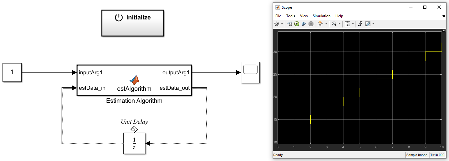
The estimation algorithm is embedded in the Simulink top level model. The output estimation bus is feed back via a unit delay. The unit delay is initialized by the initialization function on top of the estimation algorithm.
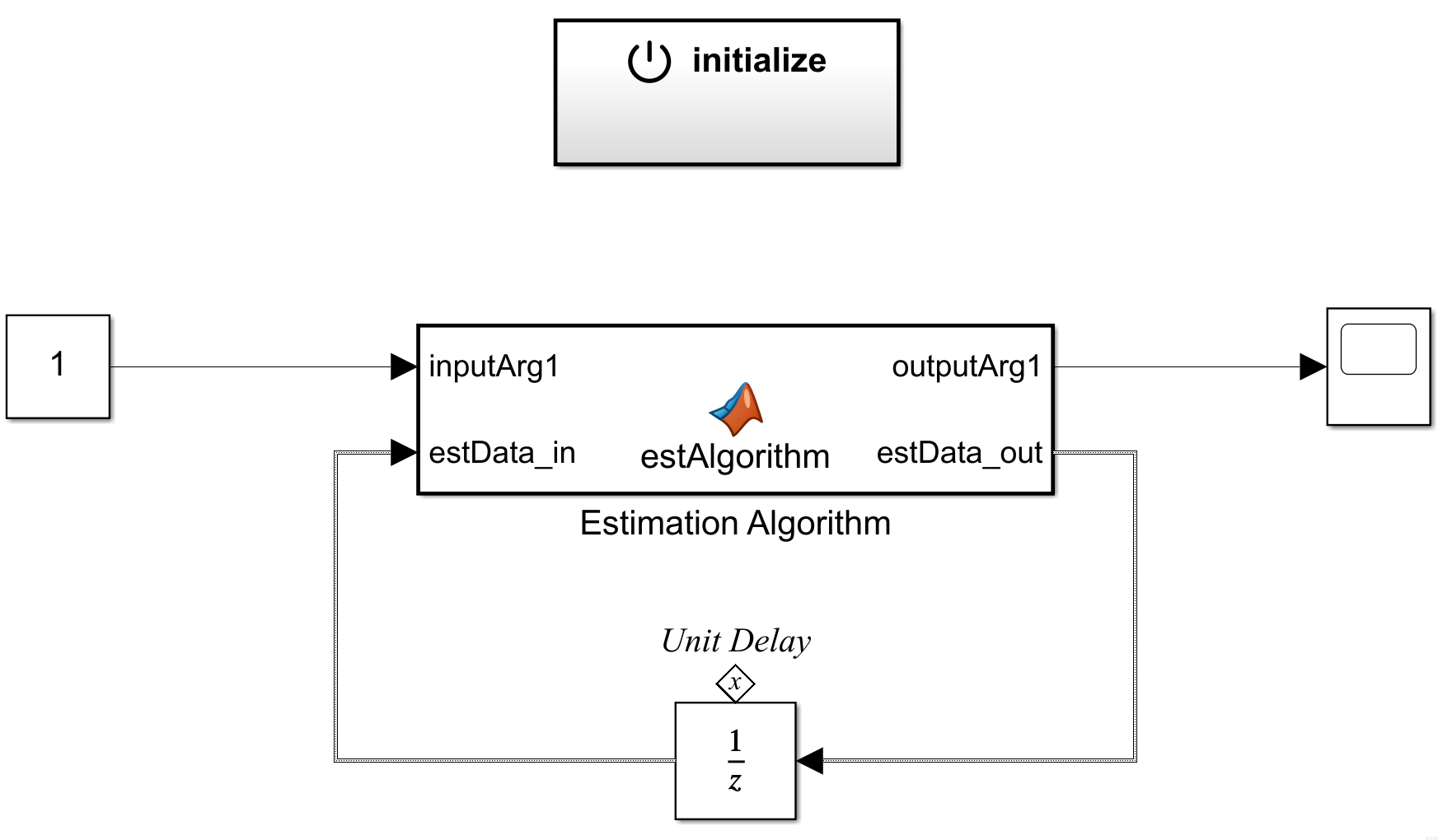
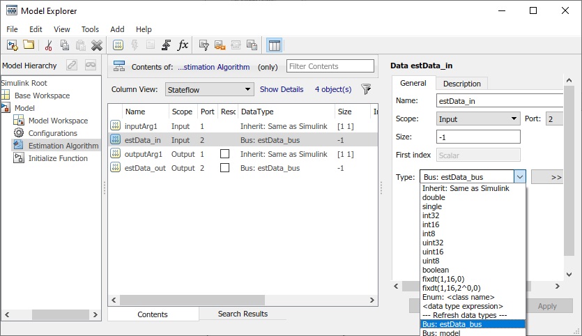
The data type of the input estData_in and output estData_out of the estimation function must be specified as estData_bus.
This is done in the Model Explorer as shown below.
Within the initialize function the state of the unit delay is set.
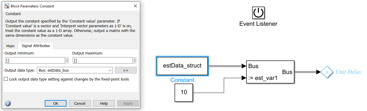
The following Figure shows how the estData_struct from the workspace is used.
Here too, it is important to specify the data type of the constant.
In this example the variable est_var1 is overwritten with 10.
In my application I overwrite the initial states of the measurement equation based on my first recorded data.
The next Figure shows the result of the simulation over 10 seconds.
At the beginning ‘est_var1’ is initialized with 10 and the estimation algorithm immediately adds 1x2, resulting in 12.
After every second another 2 is added to est_var1.
Conclusions
The complete process of creating and initializing a bus in Simulink based on a structure from the Matlab workspace is tricky. Once you are on a certain level, you can make adjustments very quickly. In my application the estimation struct has several lookup tables and state space matrices. Since C code is generated from the model that will later run on an embedded system, different optimized data types are used in the estimation struct. The data types can easily be specified in the Matlab script. They are then also used for the Simulink bus.
Below you will find the complete files to reproduce the simulation:
Matlab File
Simulink File